Update: 26th July 2015
Previous call signs: VK2DXV, VK2PJX, DK3SA and DJ0DQ.
QTH Locator: QF 44 mt
.
If you are interested in a sked on HF, VHF or UHF, send me an e-mail via
I am interested in Digital modes on the HF bands. BPSK31 is now established as the standard
digital mode. There are others, less popular but better under low s/n ratios: Olivia, Contestia, Domino EX, THROB(X), PSKFEC31, QPSK31, MFSK8 and 16. Also the good old Hellschreiber is working nicely and worth a try, especially Hell_80 and the FM modes!
Then there is JT65a - very nice in conjunction with the WSJT-X program, and also WSPR - shows how QRP power can be sufficient to hear you all over the world.
Since I don't live on top of a mountain, I am experimenting on VHF with Meteor Scatter and FSK441 , also JT65 under "normal" weak signal conditions on 6 and 2m. I am also trying to popularise the HF style digital modes for Aircraft Enhanced signals.
Digital equipment: PCs: Desktop 2.5 GHz with an integrated sound system under Linux Magaia and Lubuntu (dual boot), Laptop using Windows XP, Netbook using Linux Mandriva, together with various programs. This enables me to do most of the new digital modes, also computerised CW - which is lots of fun, if the QSO partner has a "good fist".
Other than that, I'm a bit of an all-rounder, QRV from 160m to 70cm in SSB and CW, also FM, and - if I find anyone interested in that mode - AM.
My rigs are as follows:
HF and VHF: Icom IC 706 Mk 2 and Yaesu FT 857 - Output: 100w, which I run with 50 - 75w in 100% duty cycle digital modes, 100w otherwise.
For 2m the output of the Yaesu is 50 W, the output of the Icom is 20 W, however I also have a VLA 200 amplifier.
70cm: Icom IC-490A TRTX, all mode, output: 10 W and the Yaesu FT 857, output 20W. I have also a 50 W PA.
I use various antennas - most of them home built.
I use manual ATUs for 160 to 6m. The manual variety allows one to match almost any antenna to any band. Automatic ATUs are far more restrictive!
Antenna Projects
I was always fascinated with limited space antennas, keeping in mind that on several trips aroud VK I could work DX quite regularly using mobile whips on the car. I did a few experiments with loop antennas, however I have found that short loaded verticals outperform the loop designs under normal circumstances, and are also easier to build and tune. Particularly useful are such antennas when encountering high noise levels with regular ones. For instance on 30m I have a noise level of around S8 with a regular longwire. Using a very short vertical for RX only made DX operations on that band possible. Stations that are inaudible with the big antenna (even when using all the tricks like attenuation and very low rf gain) can be copied clearly with the small one!
Important for all short antennas: Use very low loss conductors for them!
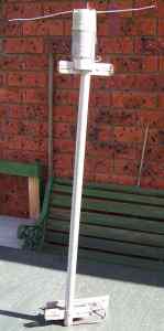
Important for tunig SWR: Check first if your cable feeds a 50 Ohm dummy load with SWR=1, if not - use one that does! Here is a prototype for 40m.
Useful bandwidth without an ATU is around 20 KHz. As an earth system I use the roof guttering plus 2 radials. When compared to a 45m loop antenna it was marginally inferior.
Possible variations:
» Parts of the loading coil could be shunted out to achieve resonance on higher bands.
» The loading coil could be of the "roller-inductor" variety. This might however cause weatherproofing problems.
» The horizontal section could consist of extendable sections to tune the antenna to different band sections.
A Caveat:
If such an antenna is appreciably longer than a metre large birds like Cockatoos find such an elevated loading coil irresistible as a perch and a toy. The results are chewed through coil windings and bent stubs. Therefore it is best to use very sturdy wire and coil base!
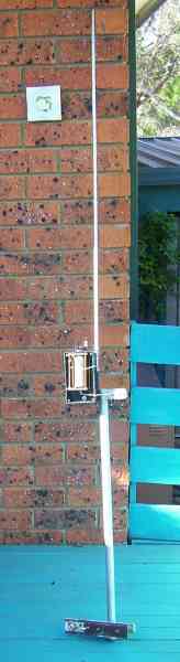
Here are 2 practical antennas like that. The first one is the 40m prototype, the second one a 2 m long centre loaded vertical with a roller-inductor loading coil:
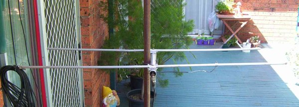
VHF and UHF antennas need not be monsters
either. Here is a 2m 2 element (driven element = 98.0 cm director = 91 cm, distance between these two = 25 cm, gamma feed distance from centre = 20 cm):
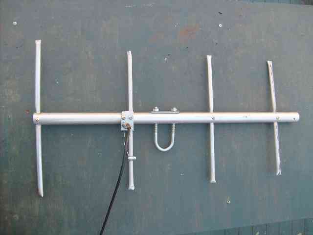
And here is a 4 element yagi for 70cm:
Dimensions: Reflector size: 33.5 cm, distance to driven element: 19.5 cm, driven element size: 30.7 cm, distance to director 1: 19 cm, director 1 size: 30 cm, distance to
director 2: 16.5 cm, director 2 size: 28.5 cm, gamma feed distance from centre: 8 cm.
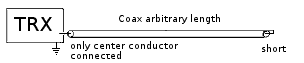
Here is the classical snake antenna, made from coax, which is open at the TRX end (only inner conductor connected to antenna plug centre) and short circuited at the far end. It can run on the ground - not necessarily in a straight line, therefore the name "Snake".
The type of "Snake Antenna" I used was a simple 15m long wire run on the ground dropping down from the rainwater guttering (which I used as counterweigh = earth). Not quite a classical type, but close enough.
I ran a few hours WSPR with 5 watts on 20 m. Here are the results:
Stations received by me Stations that received me
Needless to say, I was VERY surprised by the good performance of the snake antenna!
In the meantime I use a "true" snake antenna, 14.7m long. On the ground it achieves similar results as the previous one, it gets better when it is on the roof of the house (tiled roof, non-metallic).
Compared to my half size G5RV signals on the snake are a few dB down on receive as well as on transmit. I want to do more tests on other bands soon.
Here is a thought experiment to debunk some antenna-myths:
You have an antenna in free space, made of superconductors, which is coupled to a traveling wave feedline via a loss-free purely reactive network. The SWR on the
feedline is 1.
Q. Where will the energy supplied to the antenna go?
A. Since there is no ohmic resistance to convert it to heat, all of it will be radiated.
Q. Does the shape or form of the antenna play a role?
A. Only as far as the distribution of the radiation in different directions is concerned. The sum-total of the radiated energy remains the same.
Q. Given the above, do the currently advocated crossed-field antennas like CFL or EH give you an advantage over conventional forms, like the magnetic loop, or loaded dipoles?
A. If either antenna is built from low-loss components, the only advantages possible are radiation pattern and bandwidth.
So, can anyone find fault with these thoughts?
EH Interlude
I got interested in the EH antennas, especially since an local ham used them with great success. However the description of how these antennas are supposed to work did not make any sense to me, because electric and magnetic fields were supposedly independently generated, which of course can't be true, since these fields are always interdependent (one of the first things you learn in any Physics course). So I started experimenting.
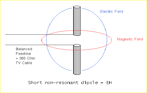
The prototype radiator consisted of two 2.5 cm diameter and 62 cm long aluminium pipes screwed onto a short wooden rod. Of course these values are totally non-critical as you will see. In principle this is a very short thick vertical dipole, which of course is not in resonance.
An electric field is generated by the voltage difference between the extreme outsides of the radiator (blue circle).
Since there is NEVER an electric field in isolation (we are talking about ELECTROMAGNETIC waves after all!), a magnetic field (red circle) is induced 90 degrees out of phase and perpendicular to the electric field.
No complicated phasing network is required, the antenna can be fed with a simple tuned feeder.
I have used this antenna, which to my big surprise was only slightly inferior to my 40m longwire antenna on 80m! On 30 and 20m however my other antennas were clearly superior.
The explanation lies in the above thought experiment: The feedline is tuned by a purely reactive ATU, there are no eddy currents generated in the Aluminium pipes which have very low resistance. Thus the energy applied to the antenna has to be radiated.
So what's the catch? If it were so simple any radiator would do the job.
The problem is the feedline. It is of course part of the antenna system - explaining the relatively large bandwidth of an EH - and it's hard to have a very low loss feedline.
The smaller the antenna the higher the currents in the feedline will be, and ohmic losses will always come into the equation. To prove this: The extreme case is that you have just the feedline and no antenna at all. Since hardly any radiation comes from the feedline (the conductors are very close together so most of the radiation in either conductor nearly cancels out the radiation in the other, thereby inducing current) most of the energy will be dissipated by very high currents creating heat in the feedline (or in more technical terms: The radiation resistance of a non-existing antenna is zero, therefore all energy has to be dissipated by the loss resistance). This of course means that the feedline should be as short as possible and be made of thick low-loss wire. And this in turn leaves high impedances to be tuned out by your ATU, which therefore should also be made of very low loss inductors and capacitors tolerant of very high voltages. It also explains why the EH performed better on 80m - the high current section on the feedline was not present - it was within the ATU. On receive signals were well down with the EH when compared to longer antennas.
In such a scenario it is tempting to omit half of the antenna and tune the other half against earth thereby utilising the feeder as additional piece of radiator. The results may actually be better this way. This is exactly what happens when you - in true EH style - introduce a 90o
phase shift in one of the legs of the feedline!
The verdict: The EH can be used and made to work using very high quality low-loss components if space is a problem. Advantageous would be to put a very
high quality ATU as close as possible to the antenna and use some kind of remote control to tune it. Then the EH just looks like a remotely tunable conventional short resonant antenna So there are no new theories required.
Antennas working on the same principle and achieving higher efficiency due to their longer radiating parts = higher radiation resistance:
The G5RV - The radiator is not in resonance on any band the antenna is supposed to work on. The combination of 300 Ω balanced feeder and coax cable used to feed the antenna is largely (the coax section will radiate of course) irrelevant for its performance.
At the moment I use a half size G5RV using 75 Ω symmetrical cable in place of the 300 Ω one. It works very well on 40, 30 and 20 metres.
The "Miscalculation Antenna" - A 2x13.5m dipole supposedly for 80, 40, 20 and 10m, fed with 300 Ω TV Cable and tuned by an ATU - very popular in the 1960s in Europe.
The "7m All-Band Vertical" - A 7m vertical without traps, fed by RG213 type coax (as short as possible) and tuned by an ATU - also popular in the 1960s. It is feasible if you have a very good counterweight or excellent ground conductivity.